Holding patterns while enroute are rare indeed. You’re held for two reasons: traffic or weather. Most spacing now is accomplished through the use of speed reductions and vectors. Occasionally, holds do occur, particularly in a terminal area, so the pilot must be able to comply. What is a holding pattern? Basically, it’s a parking lot used for separation enroute or for approach sequencing.
Holding Pattern Dimensions and Legs
What are its dimensions? They no longer are described in physical terms. Protected airspace is based on all pilots conforming to certain criteria. The outbound leg is adjusted so that the inbound leg is 1 minute long at or below 14,000 feet MSL; above 14,000 MSL 1-1/2 minutes. All turns are made at standard rate, or 30 degrees of bank, or 25 degrees of bank if a flight director is used. If these criteria are adhered to, the protected airspace will not be exceeded.
Holding Clearances
There are four basic parts to a holding clearance: a direction that identifies the course; the fix at which to hold; the course on which to hold; and an expect further clearance (EFC) time. This last item is necessary in order to direct the pilot’s actions should a two-way communications failure occur.
Pattern Visualization
After receiving the clearance, the next step is to visualize the pattern. This is accomplished by picking out the holding course from the clearance, visualizing the aircraft going inbound to the fix on the course, and, when reaching the fix, making the appropriate turn.
Pattern Entry
Next we’ll discuss the entry. The recommended entries based on the 70-degree line are just that – recommended. In the real world, the pilot can enter the hold any way he likes. It is conceded that if the most logical entry is made, it will be the one recommended, but the point is that the pilot shouldn’t get worked up into a sweat
about whether or not he’s making the “correct” entry.
Fix Types
The holding fix can be a VOR, NDB, LOM, intersection, waypoint, DME fix, or any other point in space that can be identified with navigational equipment. The near end is called the fix end and opposite this is the abeam point. Whenever the abeam point can be identified, it is the place where the timing for the outbound leg is started. The abeam point can be identified when the holding fix is a VOR, VORTAC, or NDB. If the fix is a VOR or VORTAC this point is recognized by the off indication on the TO-FROM indicator. If it were an NDB, the ADF receiver is used to identify
the abeam point. When a beam point cannot be identified, the outbound timing is started when the wings are level outbound. This situation would exist if the fix were a marker beacon or an intersection that was identified by radials that were not 90° to
each other.
Crosswind Corrections
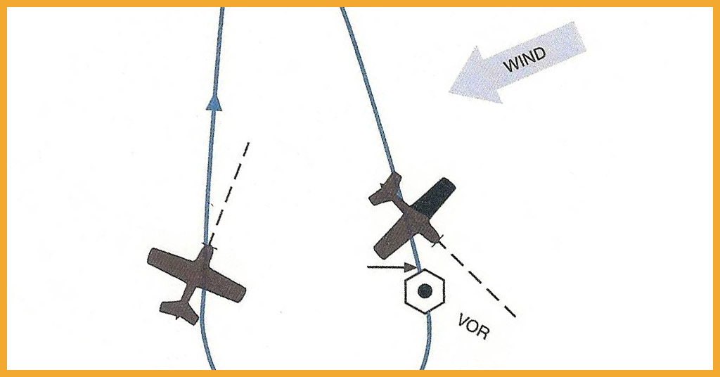
The diagram below shows the shape of a holding pattern if a crosswind is present. Note that it is egg-shaped rather than like a racetrack. This is because all turns are made at standard rate and so, the upwind and downwind turns have different radii.
Each subsequent pattern and correction must be started from exactly the same spot or the corrections are meaningless.


